Custom Search
|

|
|---|
|
|
|---|
|
|
|---|
|
Custom Search
|
|
|---|
Recommended for developers:

![]()
Lesser Goldfinch family preening
![]()
LCD Vs. CRT - Do LCDs finally match CRTs in picture quality?
ECS P965T-A Motherboard
ABIT AN8 SLI Motherboard
Foxconn 975X7AB-8EKRS2H Motherboard
Foxconn BlackOps Motherboard
![]()
My misadventures flying with Allegiant Air
![]()
The Missing Post Mystery
A post I made to a Vista newsgroup was missing from the Outlook newsreader
Where did it go?
The Missing Post Mystery Revisited
It happened again! A post I made to a Vista newsgroup was missing from the Vista Mail newsreader
Where did it go?
A Case of Maxtaken Identity
When is a hard drive not a hard drive? Find out when!
![]()
Changes to the Windows 7 Taskbar You Should Know About
Vista Image Capture 'Slipstream' SP1 and SP2 into a single Vista install disc
Detailed Instructions for Reverse Integrating SP1 and SP2 into Vista
What is RAID? Some RAID Basics
RAID 5 on a Desktop PC
How to Personalize Windows Vista
Develop and Implement a Personal Backup Plan
Ten things you can do to create better documentation
(Tech Republic)
Flash Your BIOS
Three Good Reasons for Flashing Your BIOS
Ten common mistakes you should avoid when flashing your BIOS
(Tech Republic)
Find a new dial-up ISP
Sign up for 10 free hours of NetZero access!
Create a Shutdown/Sleep/Restart or Continue Icon For the Vista Desktop
What is a computer guy doing with home remodeling projects on his Website?
The Upscale Utility Room Remodel with Catch Basin and Wraparound Ceramic Tile Wall
The Bathroom Remodel for Under $1000 Project
The Do It Yourself Bedroom Engineered Prefinished Red Oak Wood Flooring Installation From Hell
Bedroom Remodel With Wood Parquet Flooring
Use Comodo Internet Security 4.0 to Lock Down Your PC Following a Windows Install or Reinstall
![]()
The Northstar Horizon Microcomputer
![]()
Round-Tailed Ground Squirrels

Prairie Dogs

American Kestrel Falcons "Sparrow Hawk"

Arizona Sonoran Desert

Arizona Sunsets

Cienega Creek

Trains In the Desert

Desert and Mountain Flowers

Fox Squirrels

![]()
The Other Reason Why Your Irrigation Valve Might be Leaking
My Response to the Newegg Affiliates Program Changes
Playing the Rebate Game
Know the Rules Before You Play
Vista Confusion
The four questions you need to ask before buying Vista
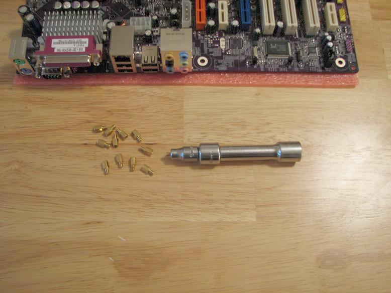
The first thing I did was to set my case on a flat surface with easy access and decent lighting. I grabbed a extender and the appropriate size socket from my socket wrench kit and counted out the number of motherboard studs needed for the ATX install. The case should have a key or cross-reference showing the code for the ATX case and the code should be marked next to each hole for the ATX form factor install.
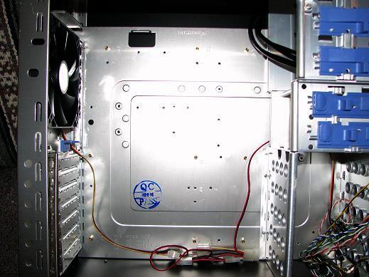
It was easy to put the studs into the appropriate holes using the hand dandy stud inserter.
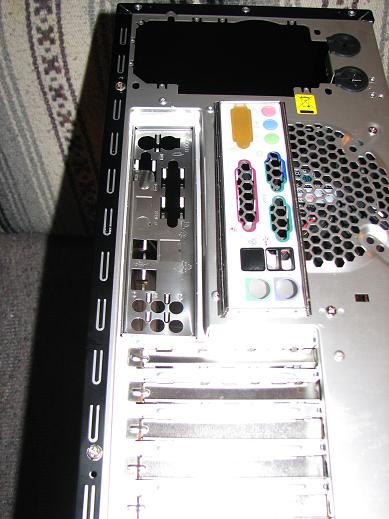
I pushed out the nice I/O shield that came with the case and inserted the flimsy custom I/O shield that came with the motherboard. Since almost no motherboards actually work with the shield that comes with the case, you will likely have to remove it. Notice the big difference in the layout of the I/O ports of the two I/O shields (the original case I/O shield is upside down in the picture).
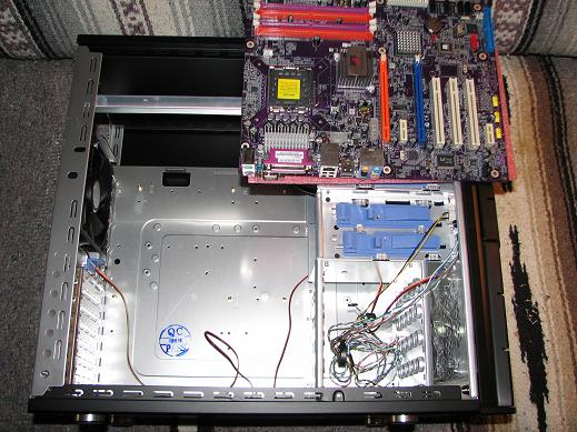
Place the motherboard in the correct orientation on the case, ready to be placed inside the case. Note that the pink plastic padding that came with the motherboard is still under the motherboard. I had two screws ready to secure the corners of the motherboard.
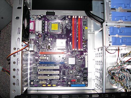
I set the motherboard into place and carefully pushed it under the I/O shield. I had to wiggle it a bit to get the I/O panel on the motherboard to be flush with the I/O shield. I next loosely secured the upper right corner and the lower right corner of the motherboard with the appropriate screws. Do not insert the other screws.
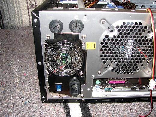
I slid and pushed the power supply snugly into place and inserted the correct screws. Note that the motherboard I/O ports are flush and aligned with the I/O shield.
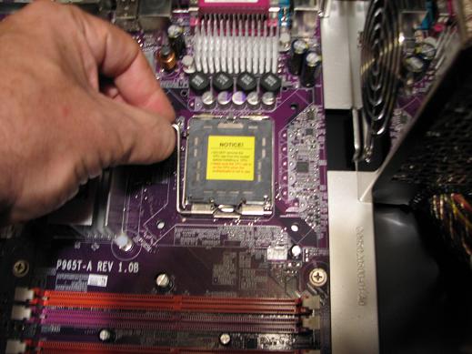
With the motherboard safely in place and secured, it was time to put the Intel Core 2 Duo processor into place. Step one: Unlatch the socket 775 CPU handle. Push down and away from the socket to release it and then pull up on the handle to completely open it.
Remove the black plastic temporary socket cover. Step two: Put your finger or thumb under the bottom of the cover and lift it off and set it aside.
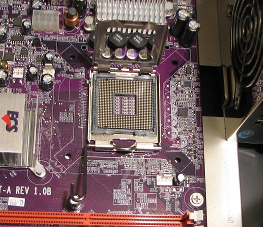
A metal bracket sits on top of the socket. Step three: Put your finger or thumb under the bottom of the bracket and pull up on the bracket in the opposite direction of the handle to open it completely.
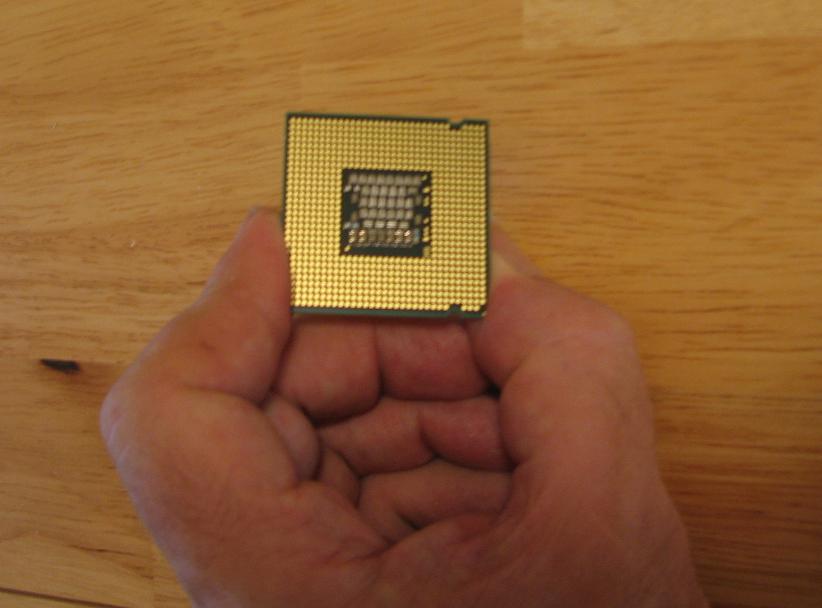
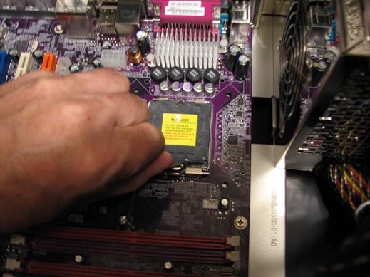
Step Four: I very carefully picked up the CPU - without touching the copper colored pads on the bottom and moved it over to the case.
Step Five: I put the CPU into place and made sure that the orientation was correct. The triangle in the corner of the CPU was matched up with the triangle in the socket. There were also two missing pads that I matched up with the socket. I double and triple checked the orientation before very carefully slipping the processor into the socket.
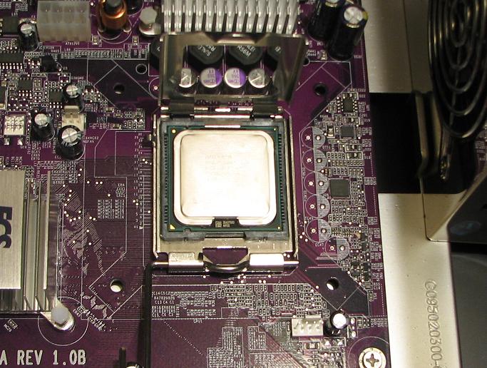
Step Six: Close the bracket and set it into place over the CPU and close the handle by pushing it down and slipping it under the latch so that it stays down in place.
Step Seven: I readied the heat sink and fan. It came already configured with thermal paste on the bottom. If you want to, this is the time to put on a different brand of thermal paste with better conductivity. The thermal paste on the heat sink should be wiped off if you are going to do this. I put the heat sink (with thermal grease) into place over the CPU and carefully pushed the plastic pins into place. You should be able to tell when the pins have cleared the underside of the motherboard. I finished this step by turning the four pushpins and locking them in place. If you want to be extra careful and you are not 100% sure that the push pins are in place, remove the motherboard and verify that the pushpins have been completely inserted and snapped into place. Now is the time to install and tighten the other motherboard screws in a random pattern, being careful not to over tighten.
The case came with a main cable stay that I placed next to the motherboard right side near the middle. I removed the paper/plastic that covered the sticky bottom and pushed it onto the case making sure that it was oriented so the closure would close perpendicularly over the cables.
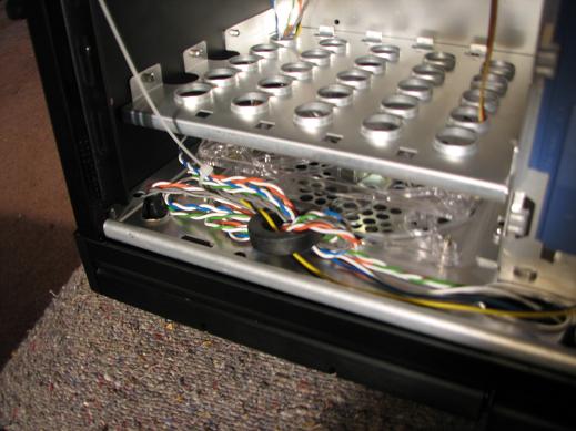
I threaded the front panel fan cable through the bottom hole of the bottom drive bay. This makes for a cleaner look with the cable hidden out of the way.
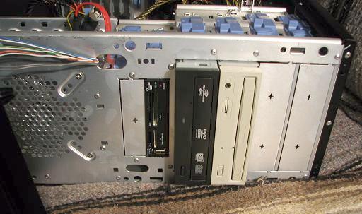
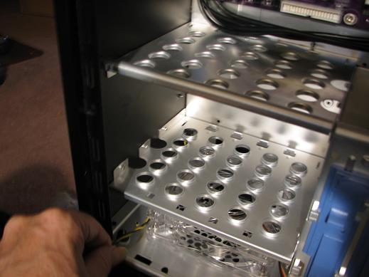
I opened the drive bay sliders by pushing them toward the rear of the case. I put the DVD/CD ROM Drive in the bottom slot of the top 5.25 inch drive bay so that the IDE cable would reach and I inserted my flash card reader into the top slot of the 3.5 inch bay so that it was close to the DVD/CD drive. I next put the plastic stays onto the hard drives and pushed them into place in the bottom drive bay in front of the 120 mm front panel fan.
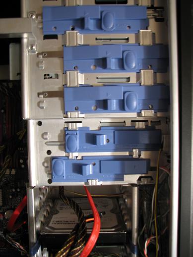
I next pushed the sliders next to the drives toward the front of the case. Being new, these were very difficult to snap into place. You may want to move them back and forth before pushing them into place. You should hear a snap when they are correctly locked into place.
I threaded the SATA power cable through the top slot of the bottom drive bay and did the same for the data cables.
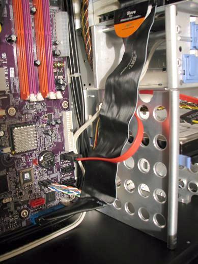
I connected all IDE and SATA cables to the drives. I connected the PSU cables and connected the USB cable, SATA cable and IDE cable to the motherboard.
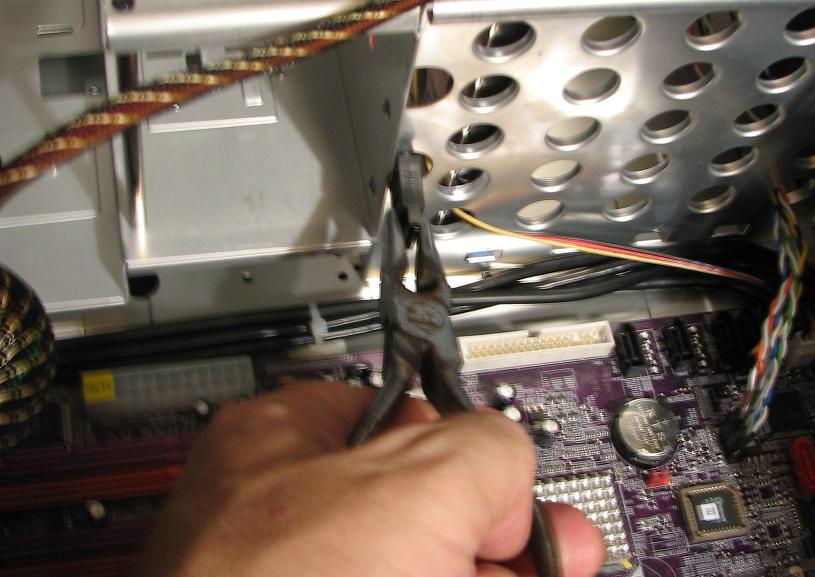
I tied down the cables routed around the motherboard and tied the cables every three or four inches with zip ties.
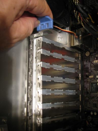
To insert the PCI or PCIe cards, release the rear panel slot closure by pulling the upper handle toward you. You may have to wiggle it to get it moving. After installing your cards, push the closure back into place. You may have to push the bottom of the closure so that it closes over the card brackets.
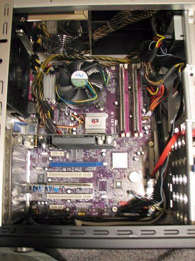
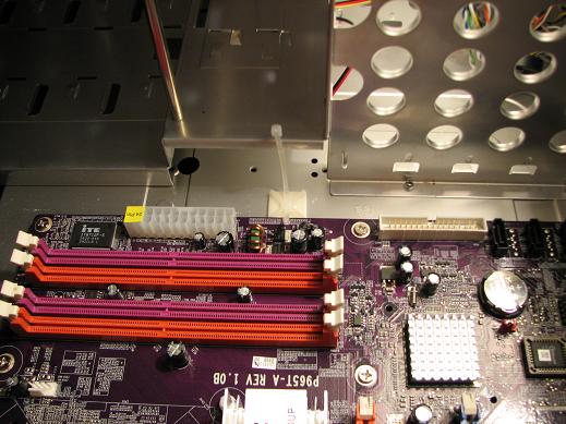
I then put the memory modules in DIMM slots one and two. The memory modules are keyed and can only be inserted one way. As in most motherboards, the DIMM slots are color coded. For the P965T-A motherboard, DIMM slots one and two are the orange slots and they are not next to each other. Carefully push the cards all the way in and lock them into place with the plastic closures. Be sure that the closure is fully inserted into the groove on the memory module.
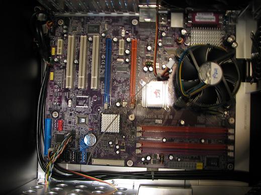
Done! As you can see, it is a very clean looking case with easy access to the motherboard.
| Pecos SoftWareWorks Home | Contact Me | Terms of Use Rev 09/30/10 | Privacy Policy Rev 05/20/09 | About Us | Site Map |
| Tweet |
|
||
|
© Copyright 2007-2015 Alan Norton None of the content may be used or reproduced without written authorization from Alan Norton. |
|||